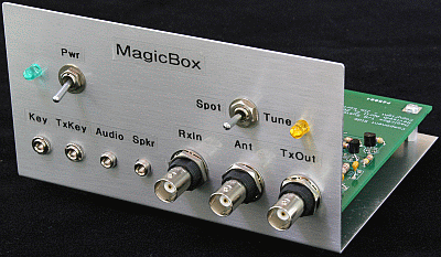
MagicBox T/R Switching System
This
system is the result of some brainstorming with Terry Fletcher,
WA0ITP and Joe Porter, W0MQY at the Dayton Hamvention in 2009. We
were talking about kits that might be suitable as revenue generators
to fund the Ozarkcon activities in 2010 and beyond. The "MagicBox"
project is the result. It is an all solid state, Transmit/Receive
switching system that allows one to connect single band CW
transmitters and receivers together to turn the pair into a
transceiving station, "like magic". The system can be used
on any band from 160 through 10 meters and up to 10-watts of RF. It can handle both solid
state and cathode keyed, tube transmitters. It supports full QSK CW
up to about 50 WPM. And, a non-QSK mode is also provided, for those
who don't like QSK CW.
This MagicBox T/R System can be ordered from the 4 State QRP Group here!!

Specifications
General
System
160
through 10 meter operation
5.3"
X 4.0 " PCB, fits TenTec TP-41 case
Approximately
120 parts
Beginning
builder skills level project
Construction
time approximately 8 hours
Power Supply 10-15 volts dc; 120 milliamps
RF Section
Receive Mode
Antenna
to Receiver Input Loss: Less than 2 dB, 1.8 - 28 MHz
Transmitter
to Receiver Input Isolation: Greater than 25 dB, 1.8 - 28 MHz
Transmit
Mode
Transmitter
Output to Antenna Loss: Less than 0.25 dB, 1.8 - 28 MHz
Antenna
to Receiver Input Isolation: Greater than 90 dB, 1.8 - 10 MHz
Greater
than 85 dB, 14 MHz
Greater
than 80 dB, 28 MHz
Audio Section (32 Ohm source and load)
Receive Mode
Receiver
Audio Loss: Less than 2 dB
Transmit
Mode
Receiver
Audio Isolation: Greater than 200 dB
Keying
QSK Mode Up to 50 WPM
Non-QSK Mode 1 second receiver delay
Transmitter Types Solid state or cathode keyed tube


Back to "Miscellaneous" page