for
Crystal Characterization & Matching
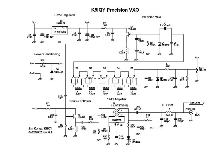
The schematic diagram for the PVXO. A detailed description of what this circuit is and how it works can be found in the Atlanticon 2002 paper entitled "Simplified Tools and Methods for Measuring Crystals" whose link is at the bottom of this page.
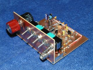
The circuitry shown above is transformed to a working instrument using Manhattan-style construction. The front panel contains the frequency control potentiometer, inductance switches, and the output BNC connector.
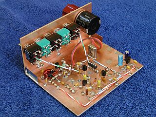
Additional details of the construction looking at the backside of the PVXO. When it was in this form, the frequency was read out on an external counter.
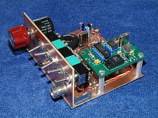
Later on in the development of the instrument, the Arizona QRP Club offered their inexpensive "Stinger Singer" CW frequeny readout designed by Dan Tayloe, N7VE. This module was added and the instrument could now read out the frequency to which it was set. A SPST push button switch was added to the front panel to control the module.
Suitable visual readouts can be obtained from the AADE and KD1JV web sites.
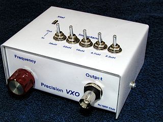
The NJ QRP Club sold 100 of the PVXO kits during 2002 and 2003. This picture shows what the finished kit looked like. Included were all components, case, and templates for doing the lettered covers.
This kit was relatively expensive to produce due to the cost of the components, especially the precision 10 turn pot, five switches, and case, and therefore didn't sell very well. However, those that bought them got a real deal considering the capabilities of the unit.
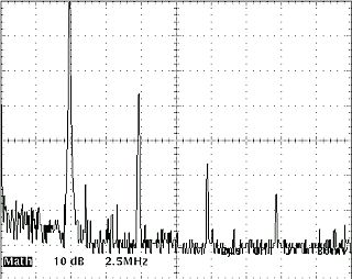
This is a spectrum plot of the PVXO with a 4.9152 MHz crystal running in the unit. The harmonics decrease as the frequency of the crystal being used increases, and the output frequency moves closer to the cutoff frequency of the output low pass filter.
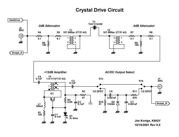
The schematic diagram of the Crystal Test Fixture (CTF) which is used in conjunction with the PVXO. This circuit provides the required drive level to the crystal being tested, as well as approximately matching the impedance the crystal under test. Data produced when using the two instruments together let one determine the characteristics of a crystal family, and then match units for subsequent use as crystal filter elements.
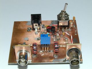
The Crystal Test Fixture was also built using Manhattan-style construction methods. Shown in the photo is the 25 Ohm cermet potentiometer used to determine the equivalent series resistance (ESR) of a crystal. The PVXO drive connects to the left BNC connector, and the external detector to the right BNC connector.
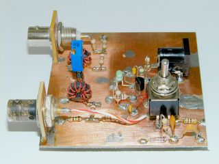
Crystal Test Fixture side view. The DPDT switch selects either an RF probe, or output directly from the RF amplifier to accomodate differing readout instruments.
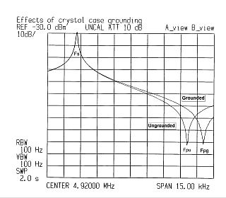
One of the more interesting (at least to me) measurements made with the PVXO and CTF was to demonstrate the effects of grounding the case of a crystal under test. As can be plainly seen, the series resonant frequency is unchanged, but the parallel resonant frequency changes about 1.5 KHz (higher) when the case is grounded. The obvious implication is that the performance of a crystal filter is also changed on its high side by moving that slope farther out from the passband.
My Atlanticon 2002 paper entitled "Simplified Tools and Methods for Measuring Crystals" can be downloaded here. The file is in .PDF format, is 1 Mb in size, and describes how to use the PVXO and CTF combo to characterize a set of crystals, and then match them for use in a crystal filter. It does not tell you how to design the filter. That task is best done using the "Filter" program, free from the AADE web site.
Parameters of several common computer crystals are here. Many have been used in my homebrew rigs. These parameters were obtained using the PVXO and CTF instruments shown above, and the procedures detailed in the 2002 Atlanticon paper.
Back to the "Test Equipment" page